
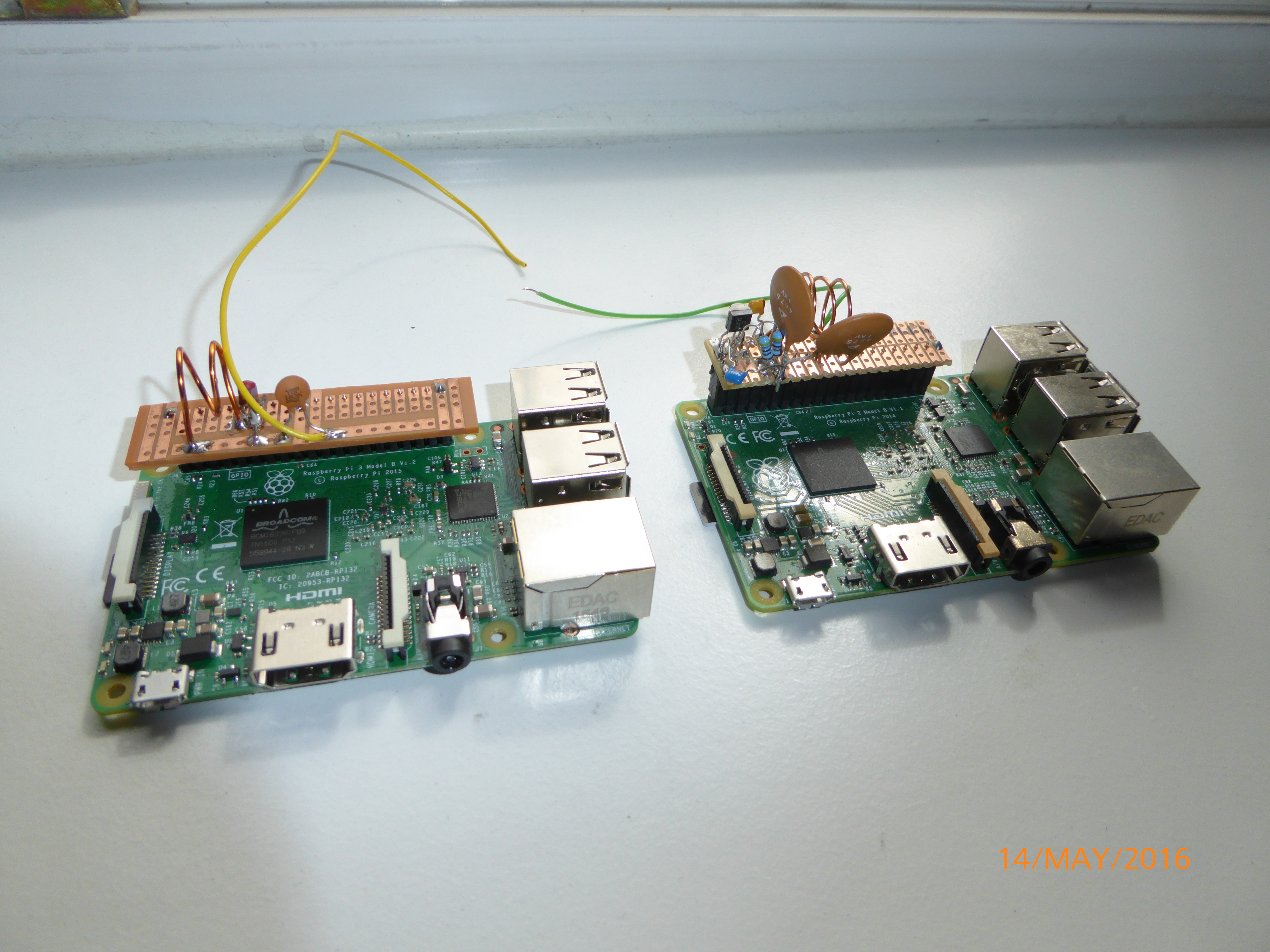
 Prototypes on perfboard
Disclaimer: The 70cm design doesn’t work as intended. The UHF GPIO signal is more like a wideband noise generator and there is no effective way of filtering the wanted signal. Don’t use it!
Simple and Effective Lowpass Filters and Amplifier for Raspberry Pi 2 and 3
The Raspberry Pi one board computer can be turned into a software defined transmitter with the software riptx and WsprryPi.
Observe that its use is only legal for licensed radio amateurs, and with a suitable low pass to supress harmonics. Here I will describe the suitable lowpasses.
Information on how to obtain this license can be found e.g. here and the test for the license can be taken for instance after one of our amateur radio courses of DK0TU. And maybe this is some motivation to obtain an amateur radio license. :-)
The output on one of the GPIO Pins is a rectangular waveform, which contains many harmonic components. Hence we need effective lowpass filters to sufficiently suppress these harmonics. An advantage here is that a small amplifier can easiliy be made using a C-class working point, meaning basically a switch, before the filter.
In this project I present a lowpass and amplifier for the 30m band and a lowpass filter for the 70cm band, but I will provide formulas such that also other bands can be used. As a lowpass filter type I chose a pi-filter, because it is simple and effective. It can be made with high quality factor Q for sufficient harmonic suppression in just one stage, it can be used for impedance transformation (important for the relatively high output impendance of the raspberry Pi, which can only deliver a few mA of current on its GPIO’s), and it leads to reasonable component values. The calculation of Pi-filters is described for instance in the ARRL Handbook 2012, Section 5.6 or in this NXP document.
I simulated the resulting circuits with the open source circuit simulator “Qucs”, or “Quite Universal Circuit Simulator”, version 0.0.18, under Ubuntu Linux.
30m Band Amplifier and Lowpass Filter
First the lowpass and amplifier for the 30m band. The following shows the 30m band amplifier, using a small signal NPN transistor in a voltage follower circuit. To protect the Raspi GPIO output, it has a 470 Ohm resistor to the base. Its Emitter drives a 47 Ohm resistor, which is the same impedance as the antenna, and hence the pi-filter becomes symmetric (its capacitors become identical). For the design it helps that rectangular waves, as they come out of the Raspberry Pi, have a first harmonic (at 20MHz) which is already significantly attenuated (see Wikipedia).
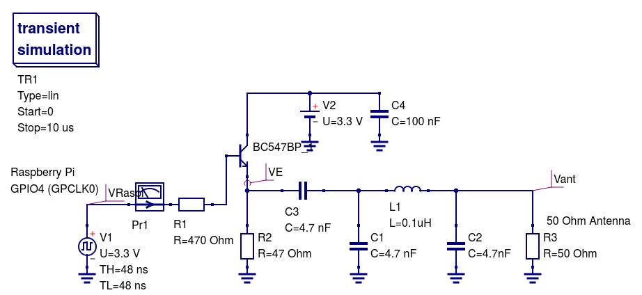 Schematic of 30m amplifier and lowpass
The schematic of the 30m amplifier and lowpass is shown in the schematic picture.
I found we need at least a quality factor Q=10 for the pi-filter to obtain at least 40 dB attenuation for the first harmonic, as required (see Bundesnetzagentur).
Then the pi-filter component values are computed according to NXP, network a), in Octave code:
1
2
3
4
5
6
7
8
9
10
11
12
13
    Q=15, R1= 50 , R2=50 , omega= 2*pi*10.1e6 ,
    XC1=R1/Q,
    %XC1 =  3.3333,
    C1=1/(omega * XC1),
    %C1 =     4.7274e-09,
    XC2=R2*sqrt((R1/R2)/((Q*Q+1)-(R1/R2))),
    %XC2 =  3.3333,
    C2=1/(omega*XC2),
    %C2 =   4.7274e-09,
    XL=(Q*R1+R1*R2/XC2)/(Q*Q+1),
    %XL =   6.6372,
    L=XL/omega,
    %L =    1.0459e-07 (100 nH),
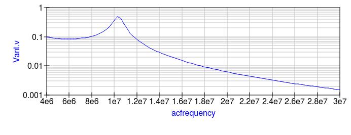 30m Frequency response
The resulting frequency response can be seen in the picture. It can be seen that we get about -40 dB attenuation at the frequency of the first harmonic at just above 20 MHz, but since this first harmonic is already attenuated from the rectangular wave form, we get more than -40 dB attenuation for the first harmonic.
To obtain the inductance of 100 nH I used the websites m0ukd.com and qsl.net/in3otd.
It turns out that using about 1 mm^2 insulated copper wire with 4 turns, a diameter of 10 mm, and a length of 10 mm results in an inductance of this 100 nH. This air coil can then be used for fine adjustment of the filter, by making the filter length longer or shorter.
This can then be build for instance on a breadboard with the suitable sockets for the Raspi.
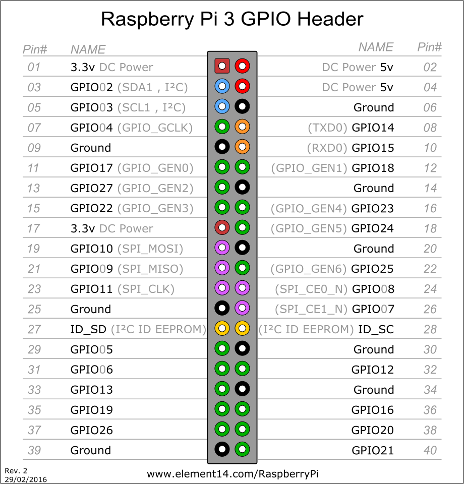 Raspi GPIO
The GPIO layout for the Raspberry Pi B+, 2, and 3 can be seen in the GPIO picture.
70cm Band Lowpass Filter
For the 70cm band I included no transistor because they become rare and expensive for that frequency. I assumed the output impedance of the Raspi at 1 kOhm (3 mA at 3V), as R1, and the antenna impedance R2= 50 Ohm. We can now compute the pi-filter - in Octave code:
1
2
3
4
5
6
7
8
9
10
11
12
13
    Q=10, R1= 1e3 , R2=50 , omega= 2*pi*433e6,
    XC1=R1/Q,
    %XC1 =  100,
    C1=1/(omega * XC1),
    %C1 =    3.6756e-12,
    XC2=R2*sqrt((R1/R2)/((Q*Q+1)-(R1/R2))),
    %XC2 =  24.845
    C2=1/(omega*XC2),
    %C2 =    1.4794e-11,
    XL=(Q*R1+R1*R2/XC2)/(Q*Q+1),
    %XL =  118.94
    L=XL/omega,
    %L =    4.3716e-08
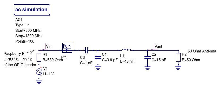 Schematic of 70cm amplifier and lowpass
The resulting schematic diagram can be seen in the schematic picture.
For N=2 turns, coil length of 5 mm, and coil diameter of 10mm, we get: L = 41nH, which is close enough. Again, the coil length is used for the fine adjustment of the filter.
Test, installation and start of the software
On 70 cm I got a strong signal with S9 + on 430.200 MHz (our club QRG), with a small 17 cm long wire antenna, within several meters. The first two harmonics (at 2x and 3x 430.200) are not detectable with my IC-T81A, not even from close :-). So more than enough damping of the harmonics.
On 30m, at 10.140 MHz, I get a strong signal when I connect a few feet of wire (S9). I found that I needed a capacitor of 100nF for the supply voltage to dampen the 1st harmonic at 2x10.140 MHz enough. With it, the first harmonic went down to S1, or 48 dB Attenuation, hence sufficient.
A picture of the 2 boards on their Rapi’s can be seen in the thumbnail picture of this article.
For my tests I used the Raspberry Pi 2 and 3, with Ubuntu Mate 16.04 as operating system.
WSPR (https://github.com/JamesP6000/WsprryPi) Output Pin: GPIO4 (GPCLK0)
Installation:
1
2
3
4
    sudo apt-get install git
    git clone https://github.com/JamesP6000/WsprryPi.git
    cd WsprryPi
    make
Test signal on 10.138 MHz:
1
    sudo ./wspr --test-tone 10.138e6
Transmit a WSPR transmission slightly off-center on 30m every 10 minutes for a total of 7 transmissions, and using a fixed PPM correction value:
1
    sudo ./wspr --repeat --terminate 7 --ppm 43.17 (your call sign) (your locator) (your power in dBm) 10140210 0 0 0 0
Transmit repeatedly on 30m with 10 dBm (10mW), use NTP based frequency offset calibration (!), and add a random frequency offset to each transmission to minimize collisions with other transmissions:
1
    sudo ./wspr --repeat --offset --self-calibration (your call sign) (your locator) (your power in dBm) 30m
Rpitx (https://github.com/F5OEO/rpitx) Output Pin: GPIO 18, means Pin 12 of the GPIO header
Installation:
1
2
3
    sudo apt-get install libsndfile1-dev imagemagick
    git clone https://github.com/F5OEO/rpitx
    ./install.sh
Take a 48 kHz sampled mono audio signal, test48khz.wav, process it with
1
    ./pifm test48.wav fm.ft
and start transmitting on our club QRG with:
1
    sudo ./rpitx -m RF -i fm.ft -f 430200 -l
Files
Qucs simulations:
Fritzing PCB layouts:
This post is licensed under CC BY 4.0 by the author. Loading...Contents
1
2
3
4
sudo apt-get install git
git clone https://github.com/JamesP6000/WsprryPi.git
cd WsprryPi
make
1
sudo ./wspr --test-tone 10.138e6
1
sudo ./wspr --repeat --terminate 7 --ppm 43.17 (your call sign) (your locator) (your power in dBm) 10140210 0 0 0 0
1
sudo ./wspr --repeat --offset --self-calibration (your call sign) (your locator) (your power in dBm) 30m
Output Pin: GPIO 18, means Pin 12 of the GPIO header
Installation:
1
2
3
sudo apt-get install libsndfile1-dev imagemagick
git clone https://github.com/F5OEO/rpitx
./install.sh
Take a 48 kHz sampled mono audio signal, test48khz.wav, process it with
1
./pifm test48.wav fm.ft
and start transmitting on our club QRG with:
1
sudo ./rpitx -m RF -i fm.ft -f 430200 -l
Files
Qucs simulations:
Fritzing PCB layouts: